Object Model
The acitoolkit object model is divided into 3 sub-areas
- Application Topology Object Model
- Interface Object Model
- Physical Topology Object Model
Application Topology
The acitoolkit defines the fabric configuration using a set of policies that describes the application logical topology.
The following diagram shows the full logical topology diagram autogenerated from the source code.
![// ACI Toolkit Class Hierarchy
digraph "ACI Toolkit Class Hierarchy" {
node [color=lightblue2 style=filled]
edge [arrowhead=none]
LogicalModel [label=LogicalModel]
Tenant [label=Tenant]
ContractSubject [label=ContractSubject]
OutputTerminal [label=OutputTerminal]
EPG [label=EPG]
IPEndpoint [label=IPEndpoint]
Filter [label=Filter]
AppProfile [label=AppProfile]
OutsideL3 [label=OutsideL3]
Tag [label=Tag]
AttributeCriterion [label=AttributeCriterion]
Taboo [label=Taboo]
Endpoint [label=Endpoint]
OutsideEPG [label=OutsideEPG]
Contract [label=Contract]
FilterEntry [label=FilterEntry]
BridgeDomain [label=BridgeDomain]
Subnet [label=Subnet]
OutsideL2 [label=OutsideL2]
OutsideL2EPG [label=OutsideL2EPG]
ContractInterface [label=ContractInterface]
Context [label=Context]
OutsideNetwork [label=OutsideNetwork]
InputTerminal [label=InputTerminal]
AnyEPG [label=AnyEPG]
LogicalModel -> Tenant
ContractSubject -> OutputTerminal
EPG -> IPEndpoint
ContractSubject -> Filter
AppProfile -> EPG
OutsideL3 -> Tag
EPG -> AttributeCriterion
Taboo -> ContractSubject
EPG -> Endpoint
OutsideEPG -> Tag
Contract -> FilterEntry
BridgeDomain -> Subnet
OutsideL2 -> OutsideL2EPG
Tenant -> ContractInterface
Contract -> ContractSubject
Context -> Tag
OutsideEPG -> OutsideNetwork
BridgeDomain -> Tag
Tenant -> Filter
Tenant -> Tag
Filter -> Tag
Tenant -> Taboo
ContractSubject -> InputTerminal
OutsideL3 -> OutsideEPG
EPG -> Tag
Taboo -> FilterEntry
Context -> AnyEPG
OutsideL2 -> Tag
Tenant -> AppProfile
Tenant -> OutsideL3
Filter -> FilterEntry
Tenant -> Contract
Tenant -> OutsideL2
Tenant -> Context
Contract -> Tag
Tenant -> BridgeDomain
}](_images/graphviz-f253fa754d285d40d4ae8c3c0553e6f57c6b9581.png)
Some of the key classes are shown and described below with the remainder described in the API Reference.
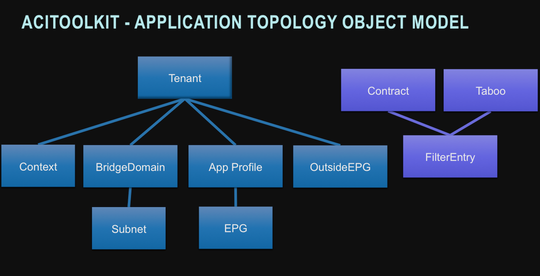
Tenant is the root class within the acitoolkit object model hierarchy. All of the application topology configuration occurs within a Tenant.
AppProfile is the Application Profile class. It contains the configuration for a given application.
EPG is the Endpoint Group class. This is the object for defining configuration that is applied when endpoints connect to the fabric.
Context is the class representing an L3 namespace (roughly, a traditional VRF in Cisco terminology).
BridgeDomain is the class representing an L2 forwarding domain (roughly, a traditional VLAN). It is associated with a single Context.
Subnet is the class representing an L3 subnet. It is associated with a single BridgeDomain.
OutsideEPG is the class representing an EPG that connects to the world outside the fabric. This is where routing protocols such as OSPF are enabled.
Contracts define the application network services being provided and consumed by EPGs. EPGs may provide and consume many contracts.
Taboos define the application network services that can never be provided or consumed by EPGs.
FilterEntry contained within either a Contract or a Taboo. Defines the traffic profile that the Contract or Taboo applies.
Interface Object Model
Interfaces provide the linkage between the application logical topology and the underlying physical network topology. The Interface set of classes are connected through a series of attachment relationships as shown in the class diagram below.
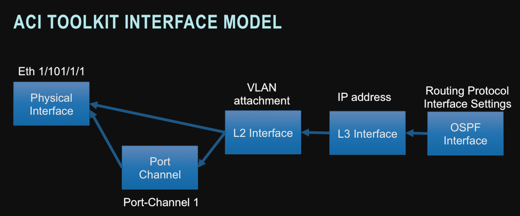
Interface class represents the Physical Interfaces. These are the objects that link the logical topology with the physical world. These objects represent the access ports on the leaf switches. These are the interfaces that the endpoints will physically attach.
PortChannel class represents the logical aggregated ethernet port formed by Link Aggregation. This is done by creating a PortChannel instance and attaching one or more Interface instances to it. When interfaces belonging to 2 separate switches are assigned to the same PortChannel, this is referred to as a VPC or Virtual Port Channel. In the acitoolkit, VPCs are also represented by the PortChannel class.
L2Interface class represents the logical L2 network attachment on an Ethernet interface. In this case, the Ethernet interface could be an Interface class instance or PortChannel class instance as both are considered representations of link layer Ethernet interfaces.
Multiple logical L2 network attachments can occur on the same Ethernet interface. When this occurs, the L2Interface instances must use different encapsulation identifiers and/or different encapsulation types. The valid encapsulation types are:
- VLAN
- VXLAN
- NVGRE
L3Interface class represents the logical L3 network attachment on an L2Interface. The L3Interface instance is where the IP address resides.
OSPFInterface class represents the logical router interface that routes from the L3Interface instance. It contains the OSPF-specific interface configuration.
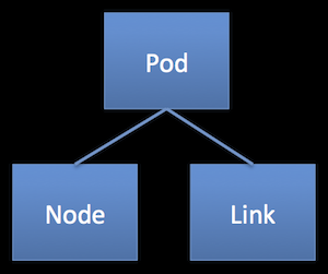
Physical Topology
The acitoolkit defines the network topology using a set of objects that represent each of the components of the topology.
These objects are connected in a hierarchy according to the following diagrams.
![// ACI Toolkit Class Hierarchy
digraph "ACI Toolkit Class Hierarchy" {
node [color=lightblue2 style=filled]
edge [arrowhead=none]
PhysicalModel [label=PhysicalModel]
Pod [label=Pod]
ExternalSwitch [label=ExternalSwitch]
Link [label=Link]
"Node " [label="Node "]
Powersupply [label=Powersupply]
Linecard [label=Linecard]
Interface [label=Interface]
Supervisorcard [label=Supervisorcard]
Fantray [label=Fantray]
Fan [label=Fan]
Systemcontroller [label=Systemcontroller]
PhysicalModel -> Pod
Pod -> ExternalSwitch
Pod -> Link
Pod -> "Node "
"Node " -> Powersupply
Linecard -> Interface
"Node " -> Linecard
"Node " -> Supervisorcard
"Node " -> Fantray
Fantray -> Fan
"Node " -> Systemcontroller
}](_images/graphviz-fa1fdfc4258da943daa88efa288572f0c634b50d.png)
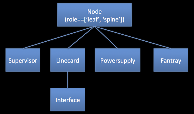
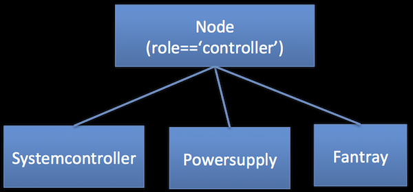
The acitoolkit.aciphysobject.Node object is used to represent both switches and controllers.
Which kind of acitoolkit.aciphysobject.Node can be determined by
looking at the role, Node.role,
attribute. Switches are Nodes with the role of ‘leaf’ or ‘spine’
and controllers are Nodes with the role of ‘controller’. Switches
are composed slightly different from controllers as shown in the
following diagram.
Pod is the class for a physical Pod. acitoolkit.aciphysobject.Pod conatins of all the
switches, links, and controllers that connected in the simple leaf-spine
fat tree topology of the ACI fabric. It does not include the
end-points or other devices that are attached to the ACI fabric.
Node is the class used to represent switches and controllers.
What role the acitoolkit.aciphysobject.Node plays in the fabric can be determined by looking at
the role attribute.
Link is the class representing links in the fabric. acitoolkit.aciphysobject.Link includes
links between leaf and spine switches as well as links from leaf
switches to controllers. Each link has two ends, the first and second
end, in no particular order. This class has methods for retrieving
the Switch, Linecard and Interface for each of the ends of the link.
Supervisorcard is the class representing the supervisor card in a
switch. acitoolkit.aciphysobject.Supervisorcard would only be a child of a Node that has the role of
‘leaf’ or ‘spine’. Each switch will have a supervisor including fixed
configuration switches that may not have a obviously physically
separate module that is a supervisor. The supervisor is where the
primary software of the switch runs.
Linecard is the class representing a linecard in a switch. The
acitoolkit.aciphysobject.Linecard is where all of the physical interfaces or ports are
attached. In modular switches, the linecard is physically obvious,
but even fixed configuration switches have a linecard where all the interfaces,
ports, reside. A specific linecard in a switch is identified by its
slot_id attribute. The slot_id of a linecard in a fixed configuration
switch is always ‘1’.
Powersupply acitoolkit.aciphysobject.Powersupply is the class representing a power supply in a node.
Fantray acitoolkit.aciphysobject.Fantray is the class representing a fan tray in a node
Systemcontroller acitoolkit.aciphysobject.Systemcontroller is the class representing a system contoller of
an APIC controller. This is the motherboard of the controller and is
a good place to understand the version of software that is running in
the controller.
Interface acitoolkit.acitoolkit.Interface described above.